

PRODUCT

Product
-
-
Communication inverter variable frequency power supply

IP-RLC PROGRAMMABLE AC LOAD
Series:
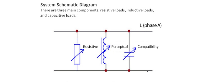
The IP-RLC series AC loads include single-phase AC loads, three-phase AC loads, RL inductive loads, RLC inductive-capacitive loads, and RCD non-linear loads. Products are widely used in daily maintenance testing, project acceptance, factory inspection testing, and product aging of various switching power supplies, medium-frequency aviation power supplies, and inverters. They can simulate the starting characteristics, stability characteristics, transient characteristics, and output parameter testing processes of purely resistive, inductive, capacitive, and mixed loads, and detect the performance of AC power supplies when connected to different loads. Power input uses optimized segmented power input to adapt to different loads and power factors.
Details
 Product Features
◆ Controlled via touchscreen + PLC, offering both local and PC control options, with corresponding host computer software provided.
◆ Inductive, capacitive, and resistive load power can be arbitrarily combined. Resistive load: 0.001KW~maximum adjustable power; Inductive load: 0.001KW~maximum adjustable power; Capacitive load: 0.001KW~maximum adjustable power. Meets the requirements of precise adjustment of AC resonance points under three-phase voltage imbalance conditions.
◆ Based on performance parameter detection requirements, discharge power can be arbitrarily combined and set via the control panel.
◆ Simulates AC power equipment resonance, effectively and accurately detecting the anti-islanding protection function of grid-connected inverters.
◆ Detects the working efficiency, maximum output power under full load, and load capacity of various inverters.
◆ Simulates various complex working environments to detect the comprehensive working performance of inverters under various conditions.
◆ Resonance Test: Setting inductive power consumption = capacitive power consumption. Theoretically, inductive and capacitive reactive power cancel each other out at resonance, and reactive power = 0.
◆ The minimum resolution of resistive, inductive, and capacitive loads is 1W, accurately simulating AC resonance and meeting the needs of inverter debugging and testing.
◆ Can measure multiple data to meet the needs of inverter testing, including: resistive current, inductive current, capacitive current, voltage, current, frequency, power, apparent power, reactive power, total voltage harmonic, total current harmonic, power factor, voltage waveform. Measurement data can be uploaded to a PC for recording and storage of the detection process data.
◆ Measurement data can be uploaded to a computer for recording and storage of the detection process data.
◆ Features both panel operation and remote control options.
◆ Features over-temperature protection, temperature setting, and temperature monitoring.
◆ Uses new resistive components, high power density, no red-hot phenomenon, long lifespan.
◆ Customizable power factor adjustable from 0.3~1.
◆ Features over-temperature protection. Temperature protection setting, temperature 0~100°C is adjustable, and real-time temperature is monitored.
◆ Uses a 7-inch LCD touchscreen for control and LCD instrument display.
◆ Uses new resistor components, high power density, no red-hot phenomenon. The unit consists of three parts: resistive load, inductive load, and capacitive load.
◆ Applicable to factory inspection, production debugging, scientific research and development, laboratory electrical characteristic testing, authoritative institution identification and testing of grid-connected inverters.
◆ Unique feature: Added power factor navigator. Users only need to input the desired power or current and power factor to form the corresponding LC value.
◆ Used by users for product acceptance and daily maintenance testing of grid-connected inverters, comprehensively and scientifically testing the power supply capacity of various inverters, and accurately providing test reports.
Reference Standards
◆ UL 1741:1999 "Inverters, Converters, and Controllers for Independent Power Systems"
◆ IEC 61727:2004 "Photovoltaic systems - Requirements for grid connection of power supply equipment"
◆ IEEE 929:2000 "Recommended Practice for Utility Interface of Photovoltaic Systems"
◆ AS 4777.2:2005 "Grid connection of power systems via inverters - Part 2: Inverter requirements"
◆ IEEE 1547:2003 "Standard for Interconnecting Distributed Resources with Electric Power Systems"
◆ IEEE 1547.1:2005 "IEEE Standard for Testing Procedures for Interconnecting Distributed Resources with Electric Power Systems"
◆ IEC62116 "Testing methods for anti-islanding of inverters used in photovoltaic grid-connected systems" established this certification technical specification.
◆ UL20/UL1054 standard switches require temperature rise testing after overload endurance.
Host Computer Software

Detailed Parameters
Product Specifications
| IP-RLC Programmable AC Load | |||||||||||
| Model | IP-RLC-10 | IP-RLC-30S | IP-RLC-60S | IP-RLC-120S | IP-RLC-200S | IP-RLC-300S | IP-RLC-600S | IP-RLC-1000S | |||
| Capacity | 10K | 30K | 60K | 120K | 200K | 300K | 600K | 1000K | |||
| Resistive Power | 11.11KW | 33.33KW | 63.33KW | 123.33KW | 213.33KW | 333.33KW | 633.33KW | 1233.33KW | |||
| Inductive Power | 11.11KVA | 33.33KVA | 63.33KVA | 123.33KVA | 213.33KVA | 333.33KVA | 633.33KVA | 1233.33KVA | |||
| Capacitive Power | 11.11Kvar | 33.33Kvar | 63.33Kvar | 123.33Kvar | 213.33Kvar | 333.33Kvar | 633.33Kvar | 1233.33Kvar | |||
| Phase A | Resistive Power | - | 11.11KW | 21.11KW | 41.11KW | 71.11KW | 111.11KW | 211.11KW | 411.11KW | ||
| Inductive Power | - | 11.11KVA | 21.11KVA | 41.11KVA | 71.11KVA | 111.11KVA | 211.11KVA | 411.11KVA | |||
| Capacitive Power | - | 11.11Kvar | 21.11Kvar | 41.11Kvar | 71.11Kvar | 111.11Kvar | 211.11Kvar | 411.11Kvar | |||
| Phase B | Resistive Power | - | 11.11KW | 21.11KW | 41.11KW | 71.11KW | 111.11KW | 211.11KW | 411.11KW | ||
| Inductive Power | - | 11.11KVA | 21.11KVA | 41.11KVA | 71.11KVA | 111.11KVA | 211.11KVA | 411.11KVA | |||
| Capacitive Power | - | 11.11Kvar | 21.11Kvar | 41.11Kvar | 71.11Kvar | 111.11Kvar | 211.11Kvar | 411.11Kvar | |||
| Phase C | Resistive Power | - | 11.11KW | 21.11KW | 41.11KW | 71.11KW | 111.11KW | 211.11KW | 411.11KW | ||
| Inductive Power | - | 11.11KVA | 21.11KVA | 41.11KVA | 71.11KVA | 111.11KVA | 211.11KVA | 411.11KVA | |||
| Capacitive Power | - | 11.11Kvar | 21.11Kvar | 41.11Kvar | 71.11Kvar | 111.11Kvar | 211.11Kvar | 411.11Kvar | |||
| Adjustment Accuracy | Resistive: 0.001KW, Inductive: 0.001KVA, Capacitive: 0.001Kvar | ||||||||||
| Operating Mode | Resistive, inductive, and capacitive loads can be freely combined. | ||||||||||
| Main Inspection Items | Can be used for the following experiments: Anti-islanding effect/efficiency test of grid-connected inverters, overload protection test, electricity meter standard, switch test, UPS test and maintenance. | ||||||||||
| Control Method | Touchscreen control or optional PC control. | ||||||||||
| Input Voltage | Can be manufactured according to customer requirements. | ||||||||||
| Supply Voltage | 1φ2W, AC220V, 50HZ | ||||||||||
| Display Measurement | Measurement Parameters | Voltage, current, frequency, active power, reactive power, power factor, voltage and current harmonic content (optional) | |||||||||
| Current Resolution | 0.001A | ||||||||||
| Current Accuracy | ±0.5% | ||||||||||
| Voltage Resolution | 0.1V | ||||||||||
| Voltage Accuracy | ±1% | ||||||||||
| Display Type | LCD Display | ||||||||||
| Remote Control Connection | 485/232C/CAN | ||||||||||
| Cooling Method | Forced Air Cooling | ||||||||||
| Protection | Overtemperature, Short Circuit, Overcurrent, Overvoltage | ||||||||||
| Operating Temperature | -10℃~+40℃ | ||||||||||
| Weight | 180 | 250 | 450 | 800 | 1000 | 1100 | 1250 | 1400 | |||
| Dimensions W×H×L | 650*1200*900 | 550*1550*700 | 940*1500*950 | 1200*1500*950 | 1100*1900*1200 | 1200*1800*1450 | 1400*1800*1700 | 1400*1800*2000 | |||
| Note: Special specifications can be customized according to customer requirements. The volume and weight are subject to the actual product. | |||||||||||
◆ Special specifications can be customized according to customer requirements (power, stepping, size, display, customized model circumference slightly longer)
◆ Ordering and Selection Instructions: To facilitate customers' better selection of our products, please provide the following parameters before ordering:
1. Rated voltage, 2. Rated power, 3. Power stepping requirements, 4. Environmental conditions of use, 5. Working mode (default long-term working mode)
Related Products


")
")
")
")

Mobile/WeChat
Mobile/WeChat
Mobile/WeChat
Add:Ninghai Meilin road tower is a pearl Tashan Industrial Zone No. 11 (IUXPOWER Electronic Technolohy)


